Iranian Classification Society Rules

< Previous | Contents | Next >
Section 18 Mechanical Joints
1801. General
The requirements of this Section apply to in accordance with the requirements in Pt
tests and inspection for the approval of mechanical joints
5, Ch 6, 104. 5 (1) of the Rules.
1802. Data to be submitted
The following reference data are to be submitted to the Society in addition to those specified in
102.
(1) Complete description of the product
(2) Typical sectional drawings with all dimensions necessary for evaluation of joint
(3) Complete specification of materials used for all components of the assembly
(4) Initial information
(A) Maximum design pressures (pressure and vacuum)
(B) Maximum and minimum design temperatures
(C) Conveyed media
(D) Intended services
(E) Maximum axial, lateral and angular deviation, allowed by manufacturer
(F) Installation details
design
1803. Type tests
1. Test items
Test items | Types of mechanical joints | Notes and references | ||||
Compression couplings and pipes unions | Slip-on joints | Expansion & Flexible | ||||
Grip type & Machine grooved type | Slip type | |||||
1 | Tightness test | ○ | ○ | ○ | ○ | Table 3.18.2 |
2 | Vibration (fatigue) test, | ○ | ○ | - | ○ | Table 3.18.2 |
3 | Pressure pulsation test1) | ○ | ○ | - | ○ | Table 3.18.2 |
4 | Burst pressure test | ○ | ○ | ○ | ○ | Table 3.18.2 |
5 | Pull-out test | ○ | ○ | - | - | Table 3.18.2 |
6 | Fire endurance test | ○ | ○ | ○ | ○ | Table 3.18.2 (If required in Pt 5, Ch 6, 104. 5(6) of the Rules) |
7 | Vacuum test | 3) ○ | ○ | ○ | - | 1304. 7 (for suction lines only) |
8 | Low temperature test | - | - | - | ○ | Table 3.18.2 (for those used at low tem- perature) |
9 | Repeated assembly test | 2) ○ | ○ | - | ○4) | Table 3.18.2 |
Abbreviations : ○ : test is required. - : test is not required. Note 1) for use in those systems where pressure pulsation other than water hammer is expected. 2) except press type. 3) except joints with metal-to-metal tightening surfaces. 4) in the case of bite joint or similar joints. | ||||||
Testing requirements for mechanical joints are to be as indicated in Table 3.18.1 Table 3.18.1 Test items for mechanical joints
116 Guidance for Approval of Manufacturing Process and Type Approval, Etc. 2015
![]()
2. Alternative testing in accordance with national or international standards may be accepted where ap- plicable to the intended use and application.
3. Unless otherwise specified, the water or oil as test fluid is to be used.
4. Selection of test specimen
(1) Test specimens are to be selected from production line or at random from stock.
(2) Where there are various sizes from type of joints requiring approval, minimum of three separate sizes representative of the range, from each type of joints are to be subject to the tests listed in Table 3.18.1
5. Mechanical joint assembly
(1) Assembly of mechanical joints should consist of components selected in accordance with preced- ing 4 (2) and the pipe sizes appropriate to the design of the joints.
(2) Where pipe material would effect the performance of mechanical joints, the selection of joints for testing is to take the pipe material into consideration.
(3) Where not specified, the length of pipes to be connected by means of the joint to be tested is to be at least five times the pipe diameter.
(4) Before assembling the joint, conformity of components to the design requirements is to be verified.
(5) In all cases the assembly of the joint shall be carried out only according to the manufacturer
instructions.
(6) No adjustment operations on the joint assembly, other than that specified by the are permitted during the test.
6. Test results acceptance criteria
(1) Where a mechanical joint assembly does not pass all or any part of the tests in two assemblies of the same size and type that failed are to be tested.
manufacturer,
Table 3.18.1,
(2) In this case, only those test which mechanical joint assembly failed in the to be repeated. In the event where one of the assemblies fails the second
type of assembly is to be considered unacceptable.
first instance, are
test, that size and
1804. Methods of tests
Test item | Kinds | Type test method |
1. Tightness test | all mechanical joints | In order to ensure correct assembly and tightness of the joints, all mechanical joints are to be subjected to a tightness test, as follows. (1) Mechanical joint assembly test specimen is to be connected to the pipe or tubing in accordance with the requirements of 1803. 5 (3) and the manufacturers instructions, filled with test fluid and de-aerated. Mechanical joints assemblies intended for use in rigid connections of pipe lengths, are not to be longitudinally restrained. Rigid connections are joints, connecting pipe length without free angular or axial movement. Pressure inside the joint assembly is to be slowly increased to 1.5 times of design pressure. This test pressure is to be retained for a minimum period of 5 minutes. In the event where there is a drop in pressure and there is visual indication of leakage, the test (including fire test) shall be repeated for two test pieces. If dur- ing the repeat test one test piece fails, the testing is regarded as having failed. Other alternative tightness test procedure, such as pneumatic test, may be accepted. (2) For compression couplings a static gas pressure test is to be carried out to demon- strate the integrity of the mechanical joints assembly for tightness under the influ- ence of gaseous media. The pressure is to be raised to maximum pressure or 7 which ever is less. (3) Where the tightness test is carried out using gaseous media as permitted in (1) above, then the static pressure test mentioned in (2) above need not be carried out. |
1. The outlines of testing methods in Table 3.18.1 are as given in Table 3.18.2. Table 3.18.2 The outlines of testing methods of mechanical joints
Guidance for Approval of Manufacturing Process and Type Approval, Etc. 2015 117
![]()
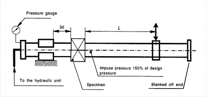
Table 3.18.2 The outlines of testing methods of mechanical joints (continued)
Test item | Kinds | Type test method |
2. Vibration (fatigue) test | General | (1) In order to establish the capability of the mechanical joint assembly to withstand fa- tigue, which is likely to occur due to vibrations under service conditions, mechanical joints assembly is to be subject to the following vibration test. (2) Conclusions of the vibration tests should show no leakage or damage, which could subsequently lead to a failure. |
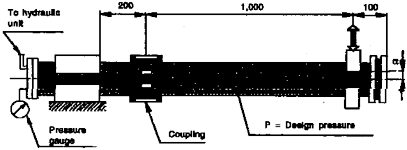
compression couplings, pipe unions, expansion & flexible joints | Compression couplings, pipe unions or other similar joints intended for use in rigid con- nections of pipe are to be tested in accordance with this method described as follows. (A) Two lengths of pipe is to be connected by means of the joint to be tested. (B) One end of the pipe is to be rigidly fixed while the other end is to be fitted to the vibration rig. (C) The test rig and the joint assembly specimen being tested is to be arranged as shown in Fig 3.18.1 Fig 3.18.1 Example of equipment for vibration(fatigue) test (D) The joint assembly is to be filled with test fluid, de-aerated and pressurised to the design pressure of the joint. (E) Pressure during the test is to be monitored. (F) In the event of drop in the pressure and visual signs of leakage the test is to be re- peated as described in 1803. 6. (G) Visual examination of the joint assembly is to be carried out for signs of damage which may eventually lead to joint leakage. (H) Re-tightening may be accepted once during the first 1000 cycles. (I) Vibration amplitude is to be within 5% of the value calculated from the following formula: × × × where: - single amplitude ( mm) - length of the pipe ( mm) - allowable bending stress in N/mm2 based on 0.25 of the yield stress - modulus of elasticity of tube material (for mild steel, E =210 kN mm ) - outside diameter of tube ( mm) (J) Test specimen is to withstand not less than cycles with frequency 20~50 Hz without leakage or damage. | |
Grip type and Machine grooved type joints | Grip type joints and other similar joints containing elastic elements are to be tested in ac- cordance with the following method. A test rig of cantilever type used for testing fatigue strength of components may be used. (A) The test specimen being tested is to be arranged in the test rig as shown in Fig 3.18.2 (B) Two lengths of pipes are to be connected by means of joint assembly specimen to be tested (C) One end of the pipe is to be rigidly fixed while the other end is to be fitted to the vibrating element on the rig. |
118 Guidance for Approval of Manufacturing Process and Type Approval, Etc. 2015
![]()
![]()
Table 3.18.2 The outlines of testing methods of mechanical joints (continued)
Test item | Kinds | Type test method |
2. Vibration (fatigue) test | Grip type and Machine grooved type joints |
Fig 3.18.2 Example of Equipment for Vibration(fatigue) test (D) The length of pipe connected to the fixed end should be kept as short as possible and in no case exceeds 200 mm. (E) Mechanical joint assemblies are not to be longitudinally restrained. (F) The assembly is to be filled with test fluid, de-aerated and pressurized to the design pressure of the joint. (G) Preliminary angle of deflection of pipe axis is to be equal to the maximum angle of deflection, recommended by the manufacturer. (H) The amplitude is to be measured at 1m distance from the center line of the joint as- sembly at free pipe end connected to the rotating element of the rig. (I) Parameters of testing are to be as indicated below and to be carried out on the same assembly (J) Pressure during the test is to be monitored. (K) In the event of a drop in the pressure and visual signs of leakage the test is to be repeated as described in 1803. 6. (L) Visual examination of the joint assembly is to be carried out for signs of damage which may eventually cause leakage. |
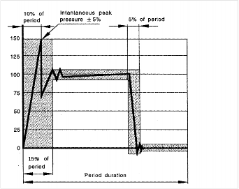
3. Pressure pulsation test | mechanical joint assembly | In order to determine capability of mechanical joint assembly to withstand pressure pulsa- tion likely to occur during working conditions, joint assemblies intended for use in rigid connections of pipe lengths, are to be tested in accordance with the following method. The mechanical joint test specimen for carrying out this test may be the same as that used in the test in 1. (1) of this Table provided it passed that test. (1) The vibration test in 2. of this Table and the pressure pulsation test are to be carried out simultaneously for compression couplings and pipe unions. (2) The mechanical joint test specimen is to be connected to a pressure source capable of generating pressure pulses of magnitude as shown in Fig 3.18.3 (3) Impulse pressure is to be raised from 0 to 1.5 times the design pressure of the joint with a frequency equal to 30~100 cycles per minute. (4) The number of cycles is not to be less than 5 × 10⁵ (5) The specimen may have small deformation whilst under test pressure, but no leakage or visible cracks are permitted. |
Number of cycles | Amplitude (mm) | Frequency (Hz) |
3 × | ± 0.06 | 100 |
± 0.5 | 45 | |
± 1.5 | 10 |
Guidance for Approval of Manufacturing Process and Type Approval, Etc. 2015 119
![]()
![]()
Table 3.18.2 The outlines of testing methods of mechanical joints (continued)
Test item | Kinds | Type test method |
3. Pressure pulsation test | mechanical joint assembly |
Fig 3.18.3 Example of Equipment for Pressure Pulsation Test |
4. Burst pressure test | mechanical joint assembly | In order to determine the capability of the mechanical joint assembly to withstand a pres- sure 4 times the design pressure, the following burst test is to be carried out. For design pressure above 20 MPa the required burst pressure will be specially considered by the Society. (1) Mechanical joint test specimen is to be connected to the pipe or tubing in accordance with the requirements of 1803. 5, filled with test fluid, de-aerated and pressurized to test pressure with an increasing rate of 10 % per minute of test pressure. (2) The mechanical joint assembly intended for use in rigid connections of pipe lengths is not to be longitudinally restrained. (3) Duration of this test is not to be less than 5 minutes at the maximum pressure. (4) This pressure value will be annotated. (5) Where consider convenient, the mechanical joint test specimen used in tightness test in 1. of this Table, same specimen may be used for the burst test provided it passed the tightness test. (6) The specimen may have small deformation whilst under test pressure, but no leakage or visible cracks are permitted. |
5. Pull-out test | mechanical joint assembly | In order to determine ability of a mechanical joint assembly to withstand axial load likely to be encountered in service without the connecting pipe from becoming detached, follow- ing pull-out test is to be carried out. (1) Pipe length of suitable size is to be fitted to each end of the mechanical joints as- sembly test specimen. (2) The test specimen is to be pressurized to design pressure. When pressure is attained, an external axial load is to be imposed with a value calculated by the following for- mula: The pressure and axial load are to be maintained for a period of 5 minutes
where: =pipe outside diameter (mm) =design pressure (N mm ) =applied axial load (N) (3) During the test, pressure is to be monitored and relative movement between the joint assembly and the pipe measured. (4) The mechanical joint assembly is to be visually examined for drop in pressure and signs of leakage or damage. (5) There are to be no movement between mechanical joint assembly and the connecting pipes. |
120 Guidance for Approval of Manufacturing Process and Type Approval, Etc. 2015
![]()
![]()
Table 3.18.2 The outlines of testing methods of mechanical joints (continued)
Test item | Kinds | Type test method |
6. Fire endurance test | mechanical joint assembly | (1) In order to establish capability of the mechanical joints to withstand effects of fire which may be encountered in service, mechanical joints are to be subjected to a fire endurance test. The fire endurance test is to be conducted on the selected test speci- mens as per the following standards. (a) KS V ISO 19921: Ships and marine technology – Fire resistance of metallic pipe components with resilient and elastomeric seals – Test methods (b) KS V ISO 19922: Ships and marine technology – Fire resistance of metallic pipe components with resilient and elastomeric seals – Requirements imposed on the test bench. (2) If the fire test is conducted with circulating water at a pressure different from the de- sign pressure of the joint (however of at least 5 bar) the subsequent pressure test is to be carried out to twice the design pressure. (3) A selection of representative nominal bores may be tested in order to evaluate the fire resistance of a series or range of mechanical joints of the same design. When a me- chanical joint of a given nominal bore (Dn) is so tested then other mechanical joints falling in the range Dn to 2xDn (both inclusive) are considered accepted. |
7. Vacuum test | mechanical joint assembly | In order to establish capability of mechanical joint assembly to withstand internal pressures below atmosphere, similar to the conditions likely to be encountered under service con- ditions, following vacuum test is to be carried out. (1) Mechanical joint assembly is to be connected to a vacuum pump and subjected to a pressure 170 hPa absolute. (2) Once this pressure is stabilized the mechanical joint assembly test specimen under test are to be isolated from the vacuum pump and this pressure is to be retained for a pe- riod of 5 minutes. (3) Pressure is to be monitored during the test. (4) No internal pressure rise is permitted. |
8. Low tem- perature test | expansion & flexible joints | The test assembly is to be connected to pipe, and is to be pressurized with hydraulic pres- sure 35 bar. The pressure is to be kept constant during 5 minutes, and the leakage is to be checked. Disassemble and assemble the test assembly after draining the water. The test assembly is to be kept in -40℃ for four days in a chamber. The test assembly is to be pressurized with air pressure 3.5 bar at this temperature, and then placed under the anti- freezing solution. In case of leakage, the test assembly is considered to have failed the test. |
9. Repeated assembly test | mechanical joint assembly | Mechanical joint test specimen are to be dismantled and reassembled 10 times in accord- ance with manufacturers instructions and then subjected to a tightness test as defined in 1 of this Table. |
Guidance for Approval of Manufacturing Process and Type Approval, Etc. 2015 121
![]()
![]()